MrCNC - part 5
My CNC machine has been receiving a bit of attention lately. It's been sitting a little forgotten for a while with a couple of problems:
- No stepper motor drivers – I used them all on my 3d printer, and then blew them all up!
- The spindle doesn't run very well – something is slightly out of alignment and so the whole thing makes a lot of noise and draws a lot of power.
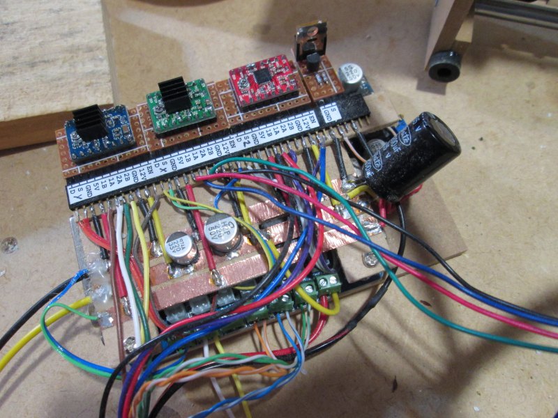
The stepper motor drivers have been replaced so that part is fixed. While I was at it, I decided to clean up the controller board. Here is what it looked like beforehand – wires and hot glue all over the place.
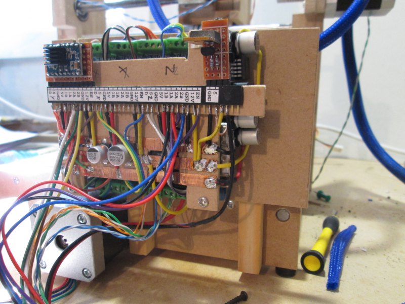
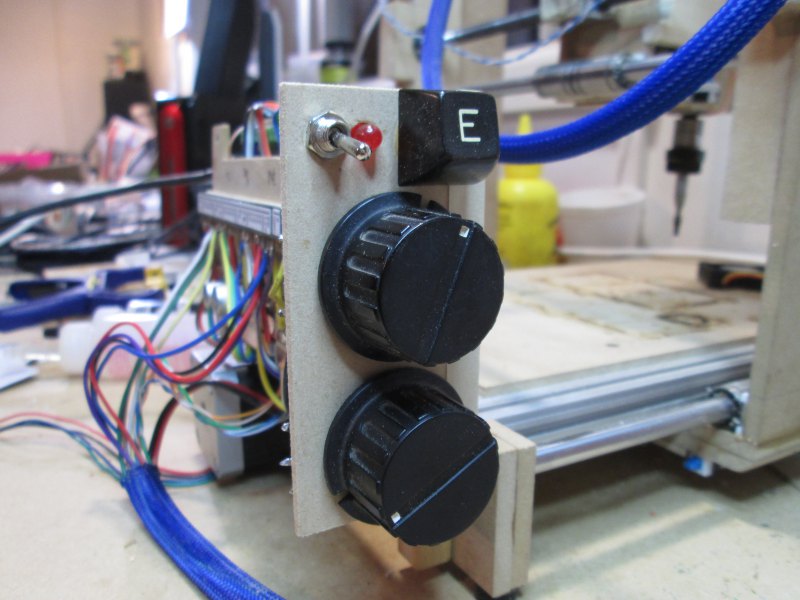
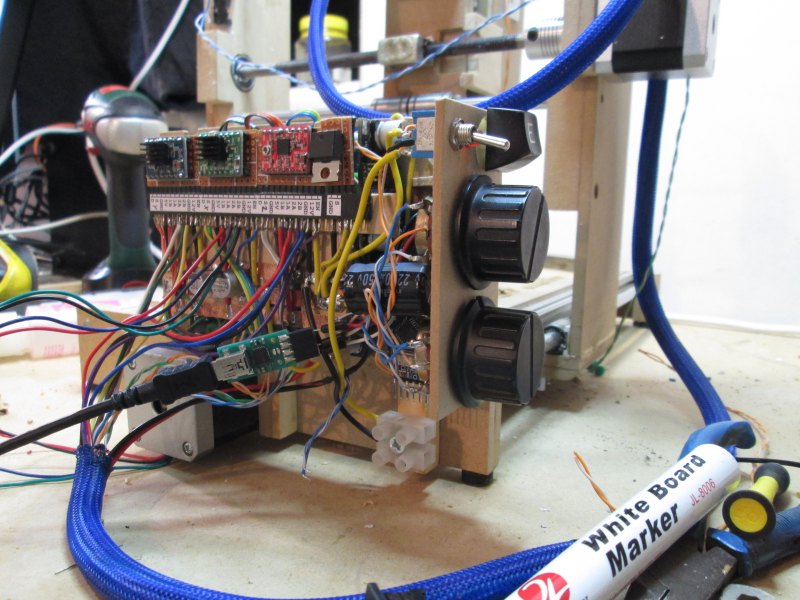
I decided to mount the board to the end of the machine. This would keep the controller off the bench and the wires nice and tidy. I also opted to add a small control panel to hold the power switch, emergency stop button, a power LED, and two speed control knobs: one for the spindle speed, and one for the feed rate (how fast the machine runs through its program).
I cut out some wood and made a new base for the controller, then glued and screwed it on.
For the control panel I made a quick mock up of what I wanted and then set about cutting and drilling.
The E switch is an interesting one; it came form an original BBC micro computer that I somehow acquired many many years ago. Each key had its own mechanical switch underneath and I've still got most of them floating around in one form or another. It's a shame I don't still have the Beeb, but I don't think it was working when I got it, and I didn't have the know-how to make it work. These days it'd be an interesting project to tackle, and I suspect a working BBC model B would fetch a pretty penny. Instead it now lives on as the emergency stop button on my CNC machine!
(Of course one day when I acquire a lot more free time than I have now, I could build my own 6502 BBC knockoff. The processors can still be bought, and an FPGA would make short work of the peripheral devices. Add some external SRAM and SPI flash and you have yourself a more-or-less equivalent device.)
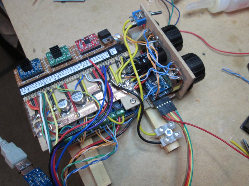
To make the knobs work I used an Arduino and TTL USB/serial adapter. The Arduino reads in the knob position, converts it to a number, runs a smoothing process on the data, and spits it out to the computer if it has changed. A total overkill for the ATmega168, which has 8x the clock speed of a BBC micro, 1/16th the RAM, and nearly the same number of pins. So what formed an entire computer back in the day, is now monitoring just 2 knobs. Why? Well it's what I had on hand.
I shoehorned the whole thing into the available space and wired up the E-switch, power LED, re-routed the power lines, etc.
I quickly whipped up a program on my PC and attempted to program it. I ran into some USB device permissions which meant I had to take a bit of a circular route to program it, and the TTL USB adapter didn't work well enough for me to program it over serial. Luckily I have a USBasp programmer for just these occasions and it quite happily programmed my board for me.
Where I ran into problems was getting serial to work. It seems that the FTDI TTL USB adapter I had is broken. I had a sneaking suspicion this was the case, and after a fair bit of fiddling I decided that was definitely the case. Into the bin it goes. I looked on TradeMe for a replacement but they started at $20, ex shipping... on eBay I can get a 10 pack for that price, including shipping! So I jerry-rigged a spare adapter in place and suddenly everything started working.
Now I just need to write the Python end of things. I found some code online that will do what I want, though it is hideously overcomplicated... I suspect I can replace their 1000s of lines with about 50 lines.
Then I just need to tidy up the wiring, give it all a clean and test, and do something about that spindle. One possible solution is to make a Dremel mount.

Leave a comment?